
Symptom
The display remains blank after the device is powered on or displays corrupted characters or pixel errors.
Verification Procedure
1. Verify the AC supply voltage.
2. Verify all DC supply voltages generated by the power supply.
3. If all supply voltages are correct, connect the Mega Tester V4 to a PC using a USB cable.
4. Power on the device.
5. Start the Firmware Loader and establish communication with the device.
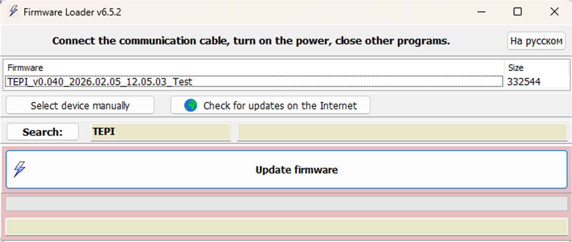
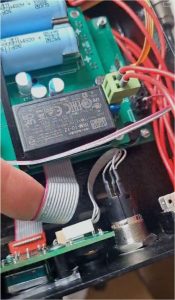
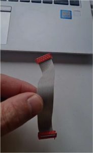
6. If the display still shows no information or displays corrupted characters or pixel errors, inspect the ribbon cable between the Front Board and the Main Board. Replace the cable if necessary.
7. As the next step, disconnect the START/STOP button cable from the Front Board and check whether the display starts operating normally.
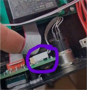
8. If the display is still blank, but the device communicates correctly with the Mega Tester PC Software and all functions operate normally, the display module may be defective.
9. Inspect the connection between the display module and the Front Board. Replace the display
module if necessary.
If none of the above procedures resolves the problem, please send the device to Opensystem West GmbH for inspection and repair.
A defective Main Board may require professional diagnosis and repair or replacement.
Address:
Opensystem West GmbH
Geierstr. 33
93309 Kelheim, Germany
Symptom:
During the RC Test, the measured capacitance is lower than expected and varies significantly between repeated measurements.
Possible Cause
A defective REL2 relay.
Verification Procedure
To verify that the Mega Tester V4 measures capacitance correctly, use one of the following methods:
Method 1 – Comparison with a Reference Instrument
• Measure the same capacitor using a calibrated capacitance meter or LCR meter.
• Compare the measured capacitance values.
Method 2 – Reference Capacitor
• Connect a known electrolytic capacitor to the Mega Tester V4.
• The capacitor’s rated voltage must be higher than the test voltage generated by the Mega Tester V4.
• Observe the correct polarity when connecting the capacitor.
• Compare the measured capacitance with the nominal value of the capacitor.
Example
• Type: Electrolytic capacitor
• Capacitance: 2.2 µF
• Rated voltage: 400 V
Corrective Action
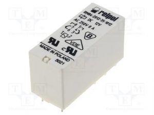
If the measured capacitance is consistently lower than the expected value or varies significantly between repeated measurements, replace relay REL2.
Replacement relay:
• REL2: RM84-2012-35-1012
Possible causes
1. Empty battery
2. Blown fuse
Actions to diagnose the appliance and rectify the defect
Check the fuse, replace it if necessary, connect the power cable and switch the appliance on again
.
Possible causes
There is an error in the microprocessor firmware
Actions to diagnose the appliance and rectify the defect
Firmware needs to be updated.
Download the latest firmware from the company’s homepage: https://opensystem-west.net/product/testing-piezo-injectors-mega-tester-v4/
>> Go to tab “Software & Firmware“
2. The device must be connected to a computer or laptop by means of a cable. You should hear the typical audible tone of the external device connection
3. Run the “Tepi_V0.00xx.exe” and carry out the update
Possible causes
Loss of contact due to transport, vibrations or other mechanical stress
Actions to diagnose the appliance and rectify the defect
Remove the cover of the unit and check that all plugs are properly connected
Select the “Stroke” test and press the “Start” button
The measurement voltage (upper value) changes according to the setting voltage, but deviates from it, check the resistors R300, R156 on the bottom side of the upper board. If the resistance is considerably higher than 50 Ohm, the resistors (size 0805, power 0,125W) have to be replaced.


The measurement voltage has a constant value and does not react to changes in the setting voltage. In this case measure the voltage as shown in the picture (on the upper and lower boards). Find a bad contact and repair it (possibly solder the pins of the connectors).


Please send the equipment to the service center for repair. Do not forget to contact us in advance and provide a copy of the sales invoice for the purchase of the device.
info@opensystem-west.com
+49 152 33 6 99 528

Possible causes
The set measurement voltage cannot be reached
Actions to diagnose the appliance and rectify the defect
Remove the housing cover, unscrew the 4 screws fixing the upper board. On the back side of the upper board, find and measure with a multimeter the resistance of the resistor R162. the nominal resistance value should be 100 ohms ± 50 ohms. If the resistance is significantly different (usually higher in case of malfunction), replace the resistor. The enclosure type is SMD 0805. Alternatively, the old resistor can be replaced with two similar resistors with a nominal resistance of 200 ohm each, in parallel (on top of each other).
Possible causes
The set measurement voltage cannot be reached
Actions to diagnose the appliance and rectify the defect
Remove the housing cover, unscrew the 4 screws fixing the upper board. On the back side of the upper board, find and measure with a multimeter the resistance of the resistor R162. the nominal resistance value should be 100 ohms ± 50 ohms. If the resistance is significantly different (usually higher in case of malfunction), replace the resistor. The enclosure type is SMD 0805. Alternatively, the old resistor can be replaced with two similar resistors with a nominal resistance of 200 ohm each, in parallel (on top of each other).
Possible causes
The set measurement voltage cannot be reached
Actions to diagnose the appliance and rectify the defect
Remove the housing cover, unscrew the 4 screws fixing the upper board. On the back side of the upper board, find and measure with a multimeter the resistance of the resistor R162. the nominal resistance value should be 100 ohms ± 50 ohms. If the resistance is significantly different (usually higher in case of malfunction), replace the resistor. The enclosure type is SMD 0805. Alternatively, the old resistor can be replaced with two similar resistors with a nominal resistance of 200 ohm each, in parallel (on top of each other).
Possible causes
Transistors Q3 and/or Q22 faulty
Actions to diagnose the appliance and rectify the defect
Replace transistors with new ones as shown in the picture.

Please send the equipment to the service center for repair. Do not forget to contact us in advance and provide a copy of the sales invoice for the purchase of the device.
info@opensystem-west.com
+49 152 33 6 99 528


